
Civic Holiday: our locations will be closed on August 3rd (Monday). All online orders placed on Monday will be processed the following day.


MACROMATIC ARP120A3R 10A DPDT 120VAC ALTERNATING RELAY WITH SWITCH
Product Details
Attributes
Features
Resources
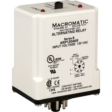
MACROMATIC ARP120A3R Duplex Alternating Relay, ARP Series, 8 pins, DPDT Configuration, 10 A at 240V AC/24V DC, 1/2 hp at 120V AC (N.O.), 1/3 hp at 120V AC (N.C.) Contact Rating, Mechanical Life of 10000000 operations, Operating Temp of -28 to 65 deg C, Storage Temp of -40 to 85 deg C, 120 VAC Control Voltage, 3 VA Load, Voltage Tolerances = AC Operation: +10/-15% of nominal at 50/60 Hz; DC Operation: +10/-15% of nominal
In the off state, both the LEAD Switch and the LAG Switch are open, the Alternating Relay is in the LOAD 1 position, and both LOAD 1 & LOAD 2 are off. The red LED marked “LOAD 1” is ON. When the LEAD Switch closes, it energizes LOAD 1. As long as the LEAD Switch remains closed, LOAD 1 remains energized. If the LAG Switch closes, it energizes LOAD 2. When the LAG Switch opens, LOAD 2 is turned off. When the LEAD Switch opens, LOAD 1 is turned off and the Alternating Relay toggles to the LOAD 2 position. The red LED marked “LOAD 2” is ON. When the LEAD Switch closes, it turns on LOAD 2. If the LAG Switch closes, it will energize LOAD 1. When the LAG Switch opens, LOAD 1 is turned off. When the LEAD Switch opens, LOAD 2 is turned off, the Alternating Relay toggles back to the LOAD 1 position, the red LED marked “LOAD 1” is ON, and the process can be repeated. NOTE: the LEAD switch must always close before the LAG switch and must always open after the LAG switch.
- For Duplex Control of two loads
- Control Voltages of 12 & 24V AC/DC and 120 & 240V AC
- Three 10A output contact configurations: SPDT, DPDT, or DPDT Cross-Wired
- Optional low profile selector switch to lock in one sequence
- 2 LEDs indicate relay status
Product Details
MACROMATIC ARP120A3R Duplex Alternating Relay, ARP Series, 8 pins, DPDT Configuration, 10 A at 240V AC/24V DC, 1/2 hp at 120V AC (N.O.), 1/3 hp at 120V AC (N.C.) Contact Rating, Mechanical Life of 10000000 operations, Operating Temp of -28 to 65 deg C, Storage Temp of -40 to 85 deg C, 120 VAC Control Voltage, 3 VA Load, Voltage Tolerances = AC Operation: +10/-15% of nominal at 50/60 Hz; DC Operation: +10/-15% of nominal
In the off state, both the LEAD Switch and the LAG Switch are open, the Alternating Relay is in the LOAD 1 position, and both LOAD 1 & LOAD 2 are off. The red LED marked “LOAD 1” is ON. When the LEAD Switch closes, it energizes LOAD 1. As long as the LEAD Switch remains closed, LOAD 1 remains energized. If the LAG Switch closes, it energizes LOAD 2. When the LAG Switch opens, LOAD 2 is turned off. When the LEAD Switch opens, LOAD 1 is turned off and the Alternating Relay toggles to the LOAD 2 position. The red LED marked “LOAD 2” is ON. When the LEAD Switch closes, it turns on LOAD 2. If the LAG Switch closes, it will energize LOAD 1. When the LAG Switch opens, LOAD 1 is turned off. When the LEAD Switch opens, LOAD 2 is turned off, the Alternating Relay toggles back to the LOAD 1 position, the red LED marked “LOAD 1” is ON, and the process can be repeated. NOTE: the LEAD switch must always close before the LAG switch and must always open after the LAG switch.
Attributes
Features
- For Duplex Control of two loads
- Control Voltages of 12 & 24V AC/DC and 120 & 240V AC
- Three 10A output contact configurations: SPDT, DPDT, or DPDT Cross-Wired
- Optional low profile selector switch to lock in one sequence
- 2 LEDs indicate relay status