
Civic Holiday: our locations will be closed on August 3rd (Monday). All online orders placed on Monday will be processed the following day.


MACROMATIC ISDUM4 DIN OR PANEL MOUNT 4 CHANNEL 8 DIP SW 102-134V AC 5A NO INTRINSICALLY SAFE RELAY
Product Details
Features
Resources
MACROMATIC ISDUM4 Intrinsically Safe Relay, ISD Series, Mechanical Life of 5000000 closures, Operating Temp of -28 to 60 deg C, Storage Temp of -55 to 85 deg C, Panel-mounted or DIN-Rail Mounting, 102-132V AC (50/60 Hz) and 10-125V DC Control Voltage, 5 VA Load
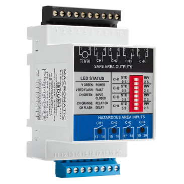
Each ISD Series product consists of 4 intrinsically safe inputs and 4 corresponding electromechanical relay outputs. With input voltage applied, the V LED will be ON (GREEN) to indicate power is applied. When the input device is closed, the input LED is ON (GREEN). When the output relay is energized, the output LED is ON (ORANGE).
These products offer four operating configurations which are user selectable and easily accessible.
ISDUM4 has an eight-position DIP-switch with configurations applied independently to each channel.
Configurations applied:
Standard Logic (DIP Switch set to “STD”):
When the input device in the hazardous area is closed, the corresponding output relay is energized. When the input device opens, the corresponding output relay will de-energize.
Inverse Logic (DIP Switch set to “INV”):
When the input device in the hazardous area is open, the corresponding output relay is energized. When the input device closes, the corresponding output relay will de-energize.
No Time Delay (DIP Switch set to “0 S”):
The output relay will have an immediate change in status in response to the input device closing or opening.
Fixed 2 Second Delay (DIP Switch set to “2 S”):
The output relay will delay 2 seconds before a change of status in response to the input device closing or opening.
- Approved for use in these hazardous environments: Class I, Div 1 (Zones 0 and 1 Canada), Groups A,B,C,D ; Class II, Div 1 (Zones 20 and 21 Canada), Groups E,F,G ; Class III, Div 1
- 4-Channel
- Isolated input terminals
- Isolated 5A relay outputs
- Pluggable terminals offer easy installation & replacement
- Universal input voltage of 102-132V AC & 10-125V DC
- Standard & inverse logic| Instantaneous & delayed response times
- LED status indicator
- UL913 8th Edition
Product Details
MACROMATIC ISDUM4 Intrinsically Safe Relay, ISD Series, Mechanical Life of 5000000 closures, Operating Temp of -28 to 60 deg C, Storage Temp of -55 to 85 deg C, Panel-mounted or DIN-Rail Mounting, 102-132V AC (50/60 Hz) and 10-125V DC Control Voltage, 5 VA Load
Each ISD Series product consists of 4 intrinsically safe inputs and 4 corresponding electromechanical relay outputs. With input voltage applied, the V LED will be ON (GREEN) to indicate power is applied. When the input device is closed, the input LED is ON (GREEN). When the output relay is energized, the output LED is ON (ORANGE).
These products offer four operating configurations which are user selectable and easily accessible.
ISDUM4 has an eight-position DIP-switch with configurations applied independently to each channel.
Configurations applied:
Standard Logic (DIP Switch set to “STD”):
When the input device in the hazardous area is closed, the corresponding output relay is energized. When the input device opens, the corresponding output relay will de-energize.
Inverse Logic (DIP Switch set to “INV”):
When the input device in the hazardous area is open, the corresponding output relay is energized. When the input device closes, the corresponding output relay will de-energize.
No Time Delay (DIP Switch set to “0 S”):
The output relay will have an immediate change in status in response to the input device closing or opening.
Fixed 2 Second Delay (DIP Switch set to “2 S”):
The output relay will delay 2 seconds before a change of status in response to the input device closing or opening.
Features
- Approved for use in these hazardous environments: Class I, Div 1 (Zones 0 and 1 Canada), Groups A,B,C,D ; Class II, Div 1 (Zones 20 and 21 Canada), Groups E,F,G ; Class III, Div 1
- 4-Channel
- Isolated input terminals
- Isolated 5A relay outputs
- Pluggable terminals offer easy installation & replacement
- Universal input voltage of 102-132V AC & 10-125V DC
- Standard & inverse logic| Instantaneous & delayed response times
- LED status indicator
- UL913 8th Edition